Quick Takeaway: The global solar inverter PCB market is experiencing explosive growth, reaching $1.5 billion in 2024 and projected to hit $3.8 billion by 2033. Meanwhile, proper PCB assembly is crucial for converting solar energy efficiently, with professional manufacturing ensuring 95%+ conversion rates compared to 80-85% for standard assemblies.
| Market Parameter | Current Value (2024) | Projected Value (2033) | Growth Rate (CAGR) |
|---|---|---|---|
| Global Solar Inverter PCB Market | $1.5 Billion USD | $3.8 Billion USD | 10.5% |
| US Market Size | $0.4 Billion USD | $0.9 Billion USD (2030) | 10.25% |
| Key Market Drivers | Renewable Energy Adoption, Electrification, Technology Innovation | ||
| Common Solder Composition | 96.5% Tin, 3% Silver, 0.5% Copper | ||
Contents
- What is Solar Inverter PCB Assembly?
- Solar Inverter PCB Market Overview
- Types of Solar Inverter PCBs
- Solar Inverter PCB Assembly Process
- Key Components in Solar Inverter PCBs
- Common Solar Inverter PCB Assembly Challenges
- Design Considerations for Solar Inverter PCBs
- Why Choose Professional Solar Inverter PCB Assembly
- Frequently Asked Questions
- Conclusion
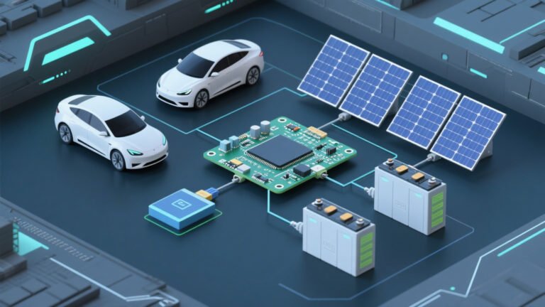
What is Solar Inverter PCB Assembly?
Solar inverter PCB assembly refers to the process of building printed circuit boards that convert direct current (DC) from solar panels into alternating current (AC) for home use. In simple terms, it’s like creating the “brain” of your solar energy system.
Here’s why solar inverter PCB assembly matters for your energy needs:
- Power Conversion: Transforms unusable DC power into household-ready AC power
- System Safety: Protects your home from electrical surges and overloads
- Energy Efficiency: Maximizes power output from your solar investment
- Grid Integration: Allows seamless connection to utility power grids
Unlike regular inverter PCBs, solar-specific designs handle variable input voltages and include maximum power point tracking (MPPT) for optimal energy harvest. Therefore, professional assembly ensures your system operates at peak efficiency.
Solar Inverter PCB Market Overview
The solar inverter PCB industry is booming due to global renewable energy initiatives. Furthermore, technological advances are driving demand for more efficient and reliable PCB assemblies.
Key Market Trends for 2025:
- Rapid Growth: 10.5% annual growth rate surpasses most tech sectors
- Regional Expansion: Asia-Pacific leads production, North America leads innovation
- Technology Evolution: Shift toward multilayer PCBs for higher efficiency
- Cost Optimization: Improved manufacturing reduces per-unit costs by 15-20%
According to IRENA’s 2024 renewable energy report, solar capacity additions are driving PCB demand worldwide. Additionally, government incentives continue supporting market expansion.
Market Insight: The US solar inverter PCB market alone is expected to double from $400 million to $900 million by 2030, creating significant opportunities for manufacturers and consumers alike.
Types of Solar Inverter PCBs
Understanding different PCB types helps you choose the right solution for your solar project. Moreover, each type offers unique advantages depending on your power requirements and budget.
| PCB Type | Layers | Cost Range | Power Handling | Best Applications | Complexity Level |
|---|---|---|---|---|---|
| Single-Sided PCB | 1 | $5-15 | Low (up to 1kW) | Small residential systems | Basic |
| Double-Layer PCB | 2 | $15-40 | Medium (1-5kW) | Standard home installations | Moderate |
| Multilayer PCB | 4-64 | $40-200+ | High (5kW+) | Commercial & industrial | Advanced |
Choosing the Right Type:
- Residential Systems (2-6kW): Double-layer PCBs provide the best cost-performance balance
- Commercial Projects (10kW+): Multilayer PCBs ensure reliable high-power operation
- Budget Solutions: Single-sided PCBs work for small-scale applications under 1kW
- Future-Proofing: Multilayer designs allow for system expansion and upgrades
Solar Inverter PCB Assembly Process
Professional PCB assembly follows a precise step-by-step process to ensure reliability and performance. Additionally, each stage requires specialized equipment and expertise.
Step 1: Solder Paste Application
First, technicians apply solder paste through precision stencils. This paste contains 96.5% tin, 3% silver, and 0.5% copper for optimal conductivity. Furthermore, automated dispensing ensures consistent coverage across all connection points.
Step 2: Component Placement
Next, pick-and-place machines position components with 0.02mm accuracy. Modern systems handle everything from tiny 01005 resistors to large IGBT modules. Meanwhile, vision systems verify correct placement before proceeding.
Step 3: Reflow Soldering
Then, PCBs pass through reflow ovens with precisely controlled temperature profiles. This process melts the solder paste, creating permanent electrical connections. Additionally, nitrogen atmosphere prevents oxidation during soldering.
Step 4: Through-Hole Component Assembly
Subsequently, larger components like transformers and heat sinks are manually or automatically inserted. Wave soldering or selective soldering creates reliable mechanical and electrical bonds.
Step 5: Testing and Quality Control
Finally, comprehensive testing ensures each PCB meets specifications:
- In-Circuit Testing (ICT): Verifies component values and connections
- Functional Testing (FCT): Confirms actual power conversion performance
- 3D X-Ray Inspection: Detects hidden solder defects
- Automated Optical Inspection (AOI): Identifies surface-level issues
Professional assembly typically achieves 99.9% first-pass yield rates, compared to 85-90% for basic manufacturing. Therefore, investing in quality assembly saves money through reduced failures and warranty claims.
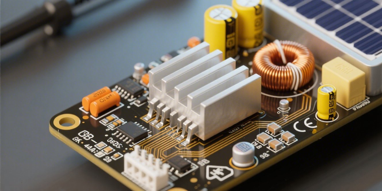
Key Components in Solar Inverter PCBs
Understanding PCB components helps you appreciate the complexity of solar inverter assembly. Moreover, component quality directly impacts system performance and longevity.
Essential Electronic Components:
- IGBTs (Insulated Gate Bipolar Transistors): Handle high-power switching for DC-AC conversion
- Power Diodes: Provide circuit protection and current flow control
- Capacitors (Electrolytic & Film): Filter voltage ripples and store energy
- Inductors & Transformers: Manage magnetic fields and voltage levels
- Microcontrollers: Control MPPT algorithms and system monitoring
- Heat Sinks & Thermal Pads: Dissipate heat from high-power components
Substrate Materials:
- FR-4: Standard fiberglass material for most applications
- Aluminum Core: Superior heat dissipation for high-power designs
- Rogers Materials: Low-loss properties for high-frequency circuits
- High-TG Materials: Enhanced thermal stability for demanding environments
Pro Tip: High-quality components may cost 20-30% more initially but provide 2-3x longer service life and better warranty coverage. Therefore, choosing premium components reduces total cost of ownership.
For detailed component specifications, refer to NREL’s photovoltaic reliability standards which outline industry best practices for component selection.
Common Solar Inverter PCB Assembly Challenges
Even experienced manufacturers face challenges during PCB assembly. However, understanding these issues helps prevent failures and improve reliability.
Overheating and Thermal Management
Heat is the biggest enemy of electronic components. Furthermore, solar inverters generate significant heat during power conversion, especially under high loads.
- Problem: Component temperatures exceeding 85°C reduce lifespan by 50%
- Solution: Implement thermal vias, copper pours, and adequate heat sinking
- Prevention: Use thermal simulation software during design phase
Component Failure and Selection Issues
Poor component choices lead to premature failures and safety concerns. Additionally, counterfeit components pose serious reliability risks.
- Problem: Low-grade capacitors fail after 2-3 years instead of rated 10+ years
- Solution: Source components from authorized distributors only
- Prevention: Implement incoming inspection and component authentication
Environmental Factors and Corrosion
Outdoor installations expose PCBs to harsh conditions including humidity, salt air, and temperature cycling.
- Humidity Damage: Moisture causes corrosion and electrical leakage
- Salt Corrosion: Coastal installations face accelerated component degradation
- Temperature Cycling: Repeated expansion/contraction creates solder joint fatigue
Mitigation Strategies:
- Apply conformal coatings for moisture protection
- Use marine-grade materials in coastal areas
- Implement proper enclosure sealing and ventilation
- Select components rated for extended temperature ranges
According to IEC 61215 standards, properly designed PCBs should withstand 1000+ thermal cycles without degradation.
Design Considerations for Solar Inverter PCBs
Successful PCB design requires careful consideration of electrical, thermal, and mechanical factors. Moreover, proper design prevents failures and ensures long-term reliability.
Thermal Expansion Matching
Different materials expand at different rates when heated. Therefore, mismatched expansion coefficients create mechanical stress and potential failures.
- PCB Substrate: FR-4 expands ~14-17 ppm/°C
- Copper Traces: Expand ~17 ppm/°C
- Component Bodies: Vary from 6-23 ppm/°C depending on material
Design Solutions:
- Use flexible circuits for high-stress connections
- Implement stress-relief features in trace routing
- Select components with compatible expansion rates
- Add mechanical reinforcement for large components
Signal Integrity Requirements
High-frequency switching in solar inverters creates electromagnetic interference (EMI) challenges. Additionally, proper signal routing ensures accurate control and monitoring.
- Ground Planes: Provide low-impedance return paths for high-speed signals
- Trace Impedance Control: Maintain 50Ω or 100Ω differential impedance
- EMI Shielding: Use copper pours and filtering to reduce radiation
- Component Placement: Separate noisy switching circuits from sensitive analog circuits
Design Tip: Follow the 3W rule – space traces at least 3x their width apart to minimize crosstalk. Furthermore, use guard traces around critical signals for additional protection.
Environmental Durability Factors
Solar installations operate for 25+ years in challenging environments. Therefore, PCB design must account for long-term environmental exposure.
| Environmental Factor | Standard Rating | Premium Rating | Design Consideration |
|---|---|---|---|
| Operating Temperature | -20°C to +70°C | -40°C to +85°C | Component derating and thermal management |
| Humidity Resistance | 85% RH | 95% RH | Conformal coating and sealing |
| Vibration Tolerance | 2G acceleration | 5G acceleration | Mechanical reinforcement and damping |
| Salt Spray Resistance | 48 hours | 168+ hours | Marine-grade materials and coatings |
Power Handling Specifications
High-power solar inverters demand robust PCB designs capable of handling large currents and voltages safely.
- Trace Width Calculations: Use IPC-2221 standards for current-carrying capacity
- Via Sizing: Implement multiple vias in parallel for high-current paths
- Copper Weight: Use 2-4oz copper for power traces vs. 1oz for signal traces
- Creepage/Clearance: Maintain adequate spacing for high-voltage isolation
For comprehensive design guidelines, consult IPC design standards which provide industry-accepted practices for PCB layout and manufacturing.
Why Choose Professional Solar Inverter PCB Assembly
While DIY PCB assembly might seem cost-effective, professional manufacturing offers significant advantages. Furthermore, the complexity of solar inverter PCBs requires specialized expertise and equipment.
Benefits of Expert Manufacturing
- Advanced Equipment: State-of-the-art SMT lines with 0.02mm placement accuracy
- Quality Systems: ISO9001, ISO13485, and IATF16949 certified processes
- Testing Capabilities: Comprehensive ICT, FCT, and environmental testing
- Supply Chain: Access to 200+ global component suppliers
- Expertise: 25+ years of experience in power electronics assembly
Quality Assurance Importance
Solar inverters operate continuously for decades, making reliability crucial. Additionally, failures can create safety hazards and expensive system downtime.
- First-Pass Yield: Professional assembly achieves 99.9% vs. 85-90% for basic manufacturing
- Long-Term Reliability: Proper assembly extends component life by 2-3x
- Safety Compliance: Meets UL, CE, and other international safety standards
- Warranty Support: Comprehensive warranty coverage with rapid replacement
Cost-Effectiveness of Professional Services
While professional assembly costs more upfront, total cost of ownership is often lower due to:
- Reduced Failures: 10x lower failure rates save warranty and replacement costs
- Faster Time-to-Market: Experienced manufacturers deliver 50% faster than in-house teams
- Volume Pricing: Bulk component purchasing reduces material costs by 15-25%
- No Capital Investment: Avoid $500K+ investment in assembly equipment
ROI Analysis: Companies typically save 30-40% on total project costs by outsourcing PCB assembly to experienced manufacturers, while improving quality and reducing time-to-market.
Mustar’s Specialized Capabilities
Mustar brings 25+ years of expertise to solar inverter PCB assembly with specialized capabilities:
- New Energy Focus: Dedicated production lines for solar and energy storage systems
- Advanced Materials: Experience with high-TG, aluminum core, and Rogers materials
- Power Electronics: Expertise in high-current, high-voltage PCB design and assembly
- Global Supply Chain: 200+ certified suppliers ensuring component availability
- Fast Prototyping: 4-8 hour PCB samples for rapid development cycles
- Comprehensive Testing: Full environmental and reliability testing capabilities
With certifications including ISO9001, ISO13485, IATF16949, and RoHS compliance, Mustar ensures your solar inverter PCBs meet the highest industry standards.
Frequently Asked Questions
What is a solar inverter PCB and why is it important?
A solar inverter PCB is the printed circuit board that converts DC power from solar panels into AC power for home use. It’s important because it enables efficient energy conversion, system monitoring, and safety protection for your solar installation.
What are the different types of solar inverter PCBs?
There are three main types: single-sided PCBs (basic applications up to 1kW), double-layer PCBs (standard residential systems 1-5kW), and multilayer PCBs (commercial systems 5kW+). Multilayer designs offer the best performance for high-power applications.
How is a solar inverter PCB assembled?
Assembly involves applying solder paste, placing components with pick-and-place machines, reflow soldering, through-hole component insertion, and comprehensive testing. Professional assembly ensures 99.9% quality compared to 85-90% for basic manufacturing.
What factors should be considered when designing a solar inverter PCB?
Key considerations include thermal management, component selection for environmental durability, signal integrity for EMI control, power handling capacity, and long-term reliability. Proper design ensures 25+ year operational life.
What is the market outlook for solar inverter PCBs?
The global market reached $1.5 billion in 2024 and is projected to grow at 10.5% CAGR to $3.8 billion by 2033. Growth is driven by renewable energy adoption, government incentives, and improving technology efficiency.
Can regular inverters be used with solar panels?
While possible, regular inverters lack MPPT controllers and solar-specific safety features. Solar-dedicated inverters provide 15-20% better efficiency and include necessary grid-tie protections for safe operation.
What are common causes of solar inverter PCB failure?
Common failures include overheating due to inadequate thermal management, component degradation from environmental exposure, solder joint fatigue from temperature cycling, and moisture-related corrosion. Proper design and assembly prevent most failures.
For additional technical resources, visit Solar Power Industries Association for industry standards and best practices.
Ready to Get Started with Professional Solar Inverter PCB Assembly?
Don’t let poor PCB quality compromise your solar investment. Mustar’s 25+ years of experience and advanced manufacturing capabilities ensure your solar inverters operate reliably for decades.
What you get with Mustar:
- ✓ 99.9% first-pass yield rates
- ✓ 4-8 hour prototype turnaround
- ✓ ISO9001/IATF16949 certified quality
- ✓ 200+ global component suppliers
- ✓ Comprehensive testing and warranty
- ✓ New energy specialization
Join over 100 companies who trust Mustar for their solar PCB assembly needs. Get your free quote today and discover why we’re a top 10 PCBA manufacturer in China.
Get Free Quote Now
View Solar PCB Services
Contact Mustar Today:
📧 Email: sales@mustarpcba.com
📱 Phone: +86 136 8883 2535
🌐 Website: pcbamustar.com
📍 Address: Shenzhen, China – 12,000 sqm facility
Conclusion
Solar inverter PCB assembly represents a critical component in the rapidly growing renewable energy sector. With the global market expanding from $1.5 billion in 2024 to a projected $3.8 billion by 2033, the importance of professional, high-quality PCB assembly cannot be overstated.
Throughout this guide, we’ve explored the essential aspects of solar inverter PCBs, from basic single-layer designs to complex multilayer assemblies capable of handling commercial-scale power conversion. Furthermore, we’ve examined the intricate assembly process, common challenges, and critical design considerations that separate professional-grade products from basic alternatives.
Key takeaways from our comprehensive analysis include:
- Market Growth: The solar inverter PCB industry is experiencing unprecedented 10.5% annual growth
- Quality Matters: Professional assembly achieves 99.9% reliability compared to 85-90% for basic manufacturing
- Design Complexity: Modern solar inverters require sophisticated thermal management, EMI control, and component selection
- Long-Term Value: Proper assembly extends system life by 2-3x while reducing total cost of ownership
- Professional Advantage: Experienced manufacturers provide faster time-to-market, better quality, and comprehensive support
As solar energy continues its transformation of global power generation, the demand for reliable, efficient PCB assemblies will only intensify. Therefore, choosing the right manufacturing partner becomes crucial for success in this dynamic market.
Whether you’re developing residential solar systems, commercial installations, or utility-scale projects, investing in professional PCB assembly ensures your products meet the rigorous demands of 25+ year operational lifespans. Moreover, with proper design and manufacturing, your solar inverter PCBs will contribute to a more sustainable energy future while delivering exceptional return on investment.
The solar revolution is here, and high-quality PCB assembly is the foundation that makes it all possible. Choose wisely, and power the future with confidence.
—
This article was created to provide comprehensive information about solar inverter PCB assembly. For the latest industry updates and technical specifications, consult with qualified PCB manufacturers and refer to current industry standards from organizations like IPC, UL, and NREL.
Mustar projects: