Contents
- Identifying the Heat Sources on Your PCBA
- PCB Layout Optimization for Thermal Balance
- Thermal Simulation & Validation: CFD Tools Matter
- Establishing a Robust Thermal Path
- Choosing the Right Thermal Interface Materials (TIM)
- Heatsinks, Shielding, and Structural Cooling
- Testing and Thermal Validation
- Intelligent Thermal Management Systems
- Material Choices & High-Tg Substrates
- Summary Table: Key Metrics for PCBA Thermal Optimization
- People Also Ask (With Expert Answers)
- Conclusion
🔍 1. Identifying the Heat Sources on Your PCBA
The first step to optimizing thermal performance is identifying heat-generating components. These usually include:
-
Power ICs and voltage regulators
-
High-frequency processors and FPGAs
-
RF modules and power amplifiers
-
LED drivers and MOSFETs
Use power consumption data and thermal resistance specifications (R<sub>θJA</sub>) to quantify heat load. Proper estimation enables more accurate thermal simulation and heat path planning.
🧭 2. PCB Layout Optimization for Thermal Balance
Component placement plays a huge role in heat dissipation:
-
Distribute heat-generating components evenly to avoid hotspots.
-
Use large copper pours and thermal vias to expand the heat dissipation area.
-
Place high-power parts near edges or near board cutouts to facilitate airflow.
🧪 Data Insight: A recent case study shows that optimizing component layout reduced post-SMT solder defects from 5% to under 1%, largely due to improved thermal equilibrium during reflow soldering.
— Source: JC-PCBA.com
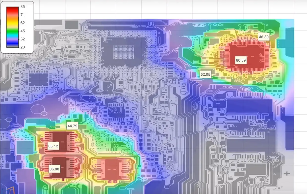
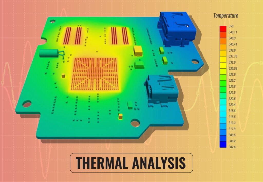
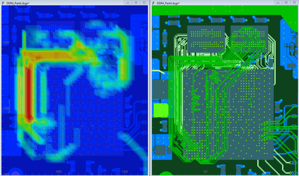
🧪 3. Thermal Simulation & Validation: CFD Tools Matter
Thermal simulation is critical for high-reliability applications (Why thermal simulation matters – Cadence Blog). Use tools like:
-
ANSYS Icepak
-
Mentor Graphics FloTHERM
-
SolidWorks Thermal Analysis
-
COMSOL Multiphysics
These platforms simulate airflow, temperature gradients, and identify heat concentration zones, allowing for design corrections early in the development cycle.
🔧 Statistic: More than 50% of electronics failures are due to thermal stress, especially in tightly packed assemblies.
— Source: Cadence PCB Design Blog, 2024
🔄 4. Establishing a Robust Thermal Path
A well-designed thermal path helps heat flow from components to the ambient environment. This includes:
-
Thermal vias under components
-
Direct heat spreading planes using copper pours
-
High-conductivity substrates, such as aluminum or metal-core PCBs (MCPCBs)
Multi-layer PCBs with internal copper planes can significantly reduce thermal resistance, especially when used with high-Tg materials.
🧱 5. Choosing the Right Thermal Interface Materials (TIM)
The choice of TIM can affect overall thermal resistance. Let’s compare common types:
| TIM Type | Typical Thermal Conductivity (W/m·K) | Notes |
|---|---|---|
| Thermal Grease | 3–5 | Excellent fill, requires reapplication |
| Thermal Pads | 1.5–4 | Easy to use, decent performance |
| Thermal Adhesives | 0.8–3 | Permanent bond, moderate performance |
| Phase-Change Materials | 1–5 | Activates with heat, great for long-term use |
📚 Reference: Wikipedia & Electronic Cooling Journal
🧊 6. Heatsinks, Shielding, and Structural Cooling
Depending on the power density, heatsinks or heat spreaders may be necessary:
-
Aluminum heatsinks offer 166–229 W/(m·K) conductivity
-
Copper heatsinks provide ~400 W/(m·K) but are heavier and costlier
-
Embedded heat pipes can transfer heat to remote cooling zones in complex enclosures
Combine structural design with airflow simulations to maximize efficiency.
🧪 7. Testing and Thermal Validation
Don’t skip this step. Use:
-
IR thermal cameras for hotspot mapping
-
Thermal couples to verify component temperatures
-
Accelerated aging tests to evaluate long-term thermal performance under real-world loads
🧠 8. Intelligent Thermal Management Systems
In complex applications, consider smart control systems:
-
Temperature sensors to trigger fan activation
-
PWM-controlled blowers for active cooling
-
Air duct design that channels cool air over the right areas
⚙ 9. Material Choices & High-Tg Substrates
Your substrate matters. Regular FR-4 has a Tg of ~130°C, which may not suffice. Instead, consider:
| Material | Tg Rating (°C) | Application |
|---|---|---|
| FR-4 | 130 | Low to medium-power circuits |
| High-Tg FR-4 | 170–180 | Industrial & automotive use |
| Ceramic | > 200 | Military, medical, high-frequency |
| MCPCB | 150–200 | LEDs, power converters |
🧾 10. Summary Table: Key Metrics for PCBA Thermal Optimization
| Design Element | Optimization Strategy | Key Benefit |
|---|---|---|
| Layout | Spread heat sources, thermal vias | Reduced hotspot formation |
| Simulation | CFD-based modeling | Early validation, fewer failures |
| TIMs | High conductivity pads/grease | Lower junction temperatures |
| Substrate | High-Tg FR-4 or MCPCB | Improved heat resistance |
| Testing | IR camera, thermocouples, aging tests | Proven performance under load |
❓ People Also Ask (With Expert Answers)
Q1: Why does a PCBA overheat?
Overheating is typically caused by poor layout, dense component placement, insufficient copper for heat conduction, or use of low thermal conductivity materials.
Q2: What are the best TIM materials for PCBA?
Silicone-based thermal grease and high-quality thermal pads are the most commonly used due to their balance of cost and performance.
Q3: What simulation software is best for thermal analysis?
ANSYS Icepak and FloTHERM are industry standards. SolidWorks Simulation and COMSOL are also great for integrated workflows.
Q4: Which PCB materials have better thermal performance?
High-Tg FR-4, aluminum-core MCPCBs, and ceramic substrates provide excellent thermal conductivity for demanding applications.
✅ Conclusion
Thermal design is no longer optional—it’s a competitive advantage. At Mustar, we don’t just manufacture PCBs. We engineer thermally reliable PCBA solutions that perform in the most demanding environments. Whether you’re working with high-power LEDs or mission-critical medical devices, our engineering team can help you optimize thermal pathways and improve product lifespan.
👉 Explore our PCBA capabilities at pcbamustar.com
Mustar projects: