🔥 Quick Decision Guide: Reflow vs Wave Soldering
Key Takeaway: Choose reflow soldering for Surface Mount Technology (SMT) components and modern electronics. Choose wave soldering for through-hole components and high-volume production. Most manufacturers today use both methods in mixed-technology assemblies.
| Factor | Reflow Soldering | Wave Soldering |
|---|---|---|
| Best For | SMT Components | Through-Hole Components |
| Speed (joints/hour) | 2,500 – 6,000 | Up to 35,000 |
| Equipment Cost | $200,000 – $500,000 | $50,000 – $150,000 |
| Energy Efficiency | Lower (repeated heating) | Higher (continuous molten solder) |
Reflow vs Wave Soldering: Complete Guide for PCB Assembly
Choosing between reflow soldering and wave soldering is one of the most important decisions in PCB assembly manufacturing. Both methods have unique advantages, and understanding their differences can save you thousands of dollars while improving product quality. In this comprehensive guide, we’ll explore everything you need to know about these two essential soldering techniques.
Contents
- What is Reflow Soldering?
- What is Wave Soldering?
- Reflow vs Wave Soldering: Key Differences
- Which Soldering Method Should You Choose?
- Cost and Efficiency Comparison
- Common Defects and Quality Control
- Lead-Free Soldering Compatibility
- Expert Recommendations from Mustar
- Conclusion
What is Reflow Soldering?
Reflow soldering is a modern PCB assembly technique that uses solder paste to attach Surface Mount Technology (SMT) components to circuit boards. Furthermore, this process involves heating the entire PCB assembly in a specialized oven to melt the solder paste and create permanent electrical connections.
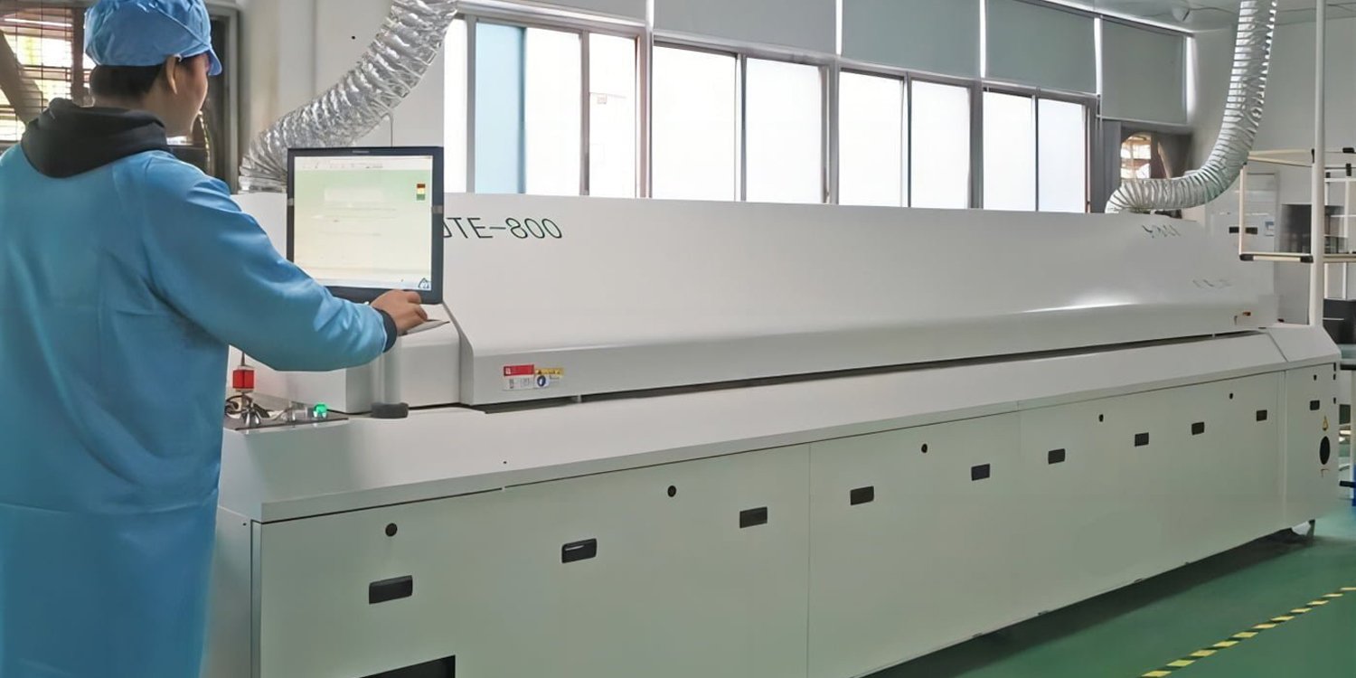
Modern reflow oven with precise temperature control zones
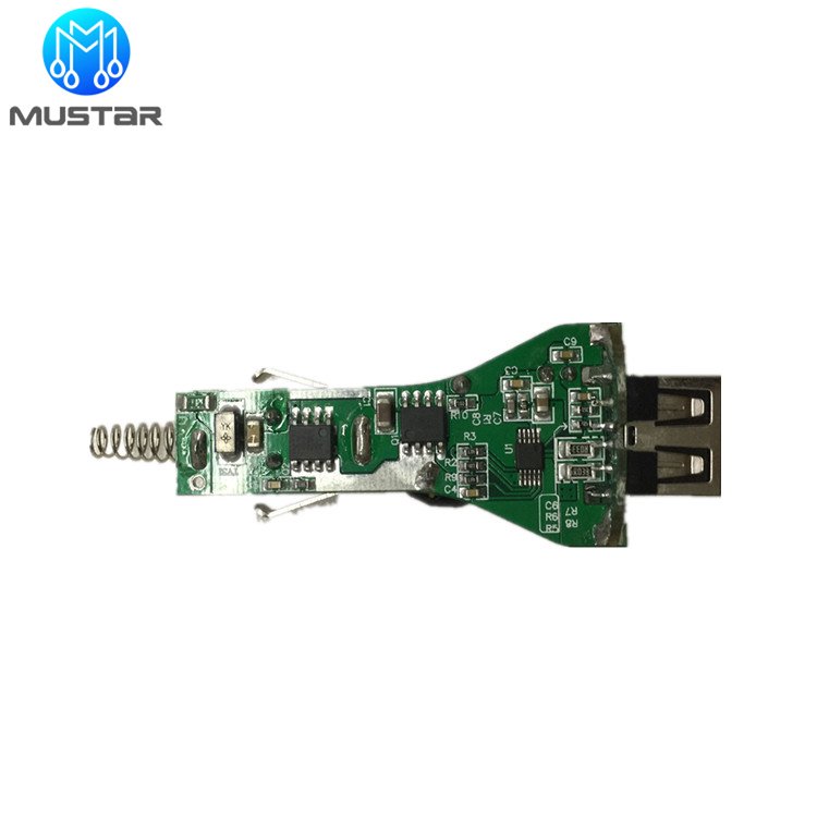
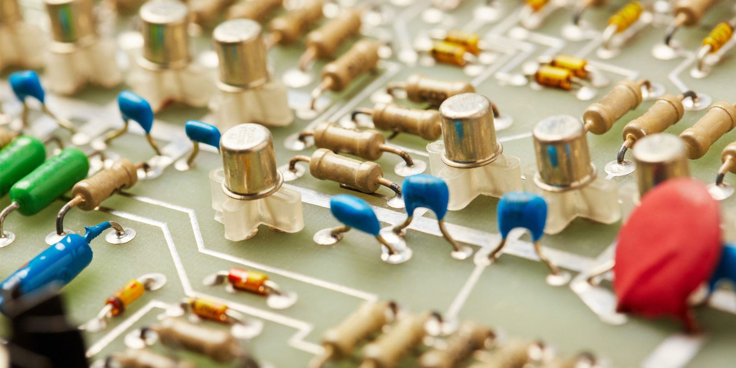
Various SMT components ready for reflow soldering
Key Steps in Reflow Soldering Process:
- Solder paste printing: Applying solder paste through stencils onto PCB pads
- Component placement: Precisely positioning SMT components using pick-and-place machines
- Reflow oven heating: Controlled heating through multiple temperature zones
- Cooling: Gradual cooling to solidify solder joints
Additionally, reflow soldering requires specialized equipment including solder paste printers, pick-and-place machines, and reflow ovens. The process excels at handling fine-pitch components and complex circuit designs that modern electronics demand.
What is Wave Soldering?
Wave soldering is a traditional yet highly effective PCB assembly method that involves passing circuit boards over a wave of molten solder. Moreover, this technique primarily serves through-hole components and some surface mount parts that can withstand the process.
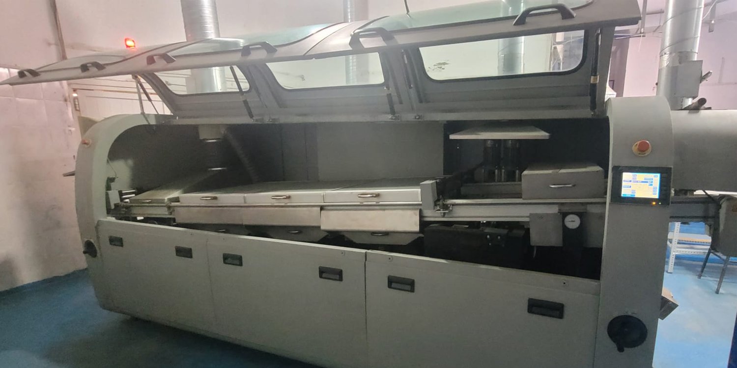
Industrial wave soldering machine in operation
Through-hole components ideal for wave soldering
Key Steps in Wave Soldering Process:
- Flux application: Spraying flux to clean component leads and PCB pads
- Preheating: Warming the PCB to prevent thermal shock
- Wave contact: PCB passes over molten solder wave
- Cooling: Natural air cooling to solidify joints
Furthermore, wave soldering machines maintain a constant temperature of molten solder, making them ideal for high-volume production. The process works exceptionally well with through-hole technology (THT) components like resistors, capacitors, and connectors.
Reflow vs Wave Soldering: Key Differences
Understanding the fundamental differences between reflow soldering vs wave soldering helps manufacturers choose the right approach for their specific needs. Let’s examine the most important distinctions:
| Parameter | Reflow Soldering | Wave Soldering |
|---|---|---|
| Suitable Components | Surface Mount Technology (SMT) | Through-Hole Technology (THT), DIP |
| Process Steps | Paste printing → Component placement → Reflow oven → Cooling | Flux spraying → Preheating → Solder wave → Cooling |
| Throughput (joints/hr) | 2,500 – 6,000 | Up to 35,000 |
| Equipment Cost | $200,000 – $500,000 | $50,000 – $150,000 |
| Floor Space Required | Typically > 25 meters | Compact inline, < 10 meters |
| Energy Consumption | High (repeated heating cycles) | More efficient (constant molten solder) |
| Common Defects | Tombstoning, insufficient paste, voids | Shadowing, flux residue, bridging |
| Lead-Free Compatibility | Easily adapted with modified profiles | Requires higher temps, nitrogen curtains |
“The choice between reflow and wave soldering often depends on your component mix. Modern electronics typically require both methods in a mixed-technology approach.” – PCB Assembly Expert
Which Soldering Method Should You Choose?
Selecting between reflow vs wave soldering requires careful consideration of your specific requirements. Here’s a practical decision framework to guide your choice:
🎯 Choose Reflow Soldering When:
- Component types: Your design uses primarily SMT components (resistors, capacitors, ICs)
- Precision requirements: Fine-pitch components like BGA, QFN, or 01005 packages
- Modern electronics: Smartphones, tablets, IoT devices, and compact designs
- Quality demands: High-reliability applications requiring precise solder joint formation
⚡ Choose Wave Soldering When:
- Component types: Through-hole components dominate your design
- High volume: Large production runs where speed is crucial
- Cost sensitivity: Lower equipment investment is priority
- Traditional designs: Power supplies, industrial controls, automotive applications
🔄 Consider Mixed Technology When:
Many modern PCB assemblies benefit from combining both methods. For instance, you might use reflow soldering for SMT components first, then wave soldering for through-hole connectors and larger components.
Industry-Specific Recommendations:
- Automotive: Mixed technology approach for reliability and durability
- Medical: Reflow soldering for precision, wave for power components
- Consumer Electronics: Primarily reflow soldering for miniaturization
- Industrial: Wave soldering for robust connections and harsh environments
Cost and Efficiency Comparison
When comparing reflow soldering vs wave soldering costs, manufacturers must consider both initial investment and operational expenses. Therefore, let’s break down the key financial factors:
Equipment Investment Analysis:
Reflow Soldering Costs
- Solder paste printer: $50,000 – $150,000
- Pick-and-place machine: $100,000 – $300,000
- Reflow oven: $50,000 – $200,000
- Total: $200,000 – $650,000
Wave Soldering Costs
- Wave soldering machine: $50,000 – $150,000
- Flux application system: $10,000 – $30,000
- Conveyor system: $5,000 – $15,000
- Total: $65,000 – $195,000
Operational Efficiency Metrics:
Beyond initial costs, operational efficiency significantly impacts long-term profitability. Industry studies show that wave soldering typically offers:
- Higher throughput: Up to 6x faster joint formation
- Lower labor costs: Less complex setup and operation
- Reduced floor space: More compact production lines
- Energy efficiency: Continuous operation vs. batch processing
However, reflow soldering provides:
- Higher component density: More circuits per board
- Better yields: Precise control reduces defects
- Future-proof investment: Supports evolving SMT technology
Common Defects and Quality Control
Understanding defect patterns in both reflow and wave soldering helps manufacturers implement effective quality control strategies. Moreover, proper defect prevention saves significant costs in rework and customer returns.
Reflow Soldering Defects:
- Tombstoning: Components stand upright due to uneven heating
- Insufficient solder: Poor wetting or inadequate paste volume
- Solder voids: Gas entrapment during reflow process
- Component shift: Movement during reflow due to thermal expansion
Wave Soldering Defects:
- Shadowing: Components blocking solder flow to nearby areas
- Flux residue: Improper cleaning leaving corrosive materials
- Solder bridging: Unintended connections between adjacent pads
- Poor hole fill: Insufficient solder penetration in through-holes
Quality Control Best Practices:
Professional PCB manufacturers like Mustar implement comprehensive quality control measures including:
- 3D SPI (Solder Paste Inspection): Verifying paste volume and placement
- AOI (Automated Optical Inspection): Detecting component placement and solder joint quality
- X-Ray inspection: Identifying hidden defects in BGA and complex joints
- ICT (In-Circuit Testing): Functional verification of assembled circuits
Furthermore, IPC-A-610 standards provide industry-accepted criteria for solder joint acceptability in both reflow and wave soldering processes.
Lead-Free Soldering Compatibility
Environmental regulations like RoHS (Restriction of Hazardous Substances) have made lead-free soldering mandatory for many applications. Consequently, understanding how both soldering methods adapt to lead-free requirements is crucial for compliance.
Reflow Soldering Lead-Free Adaptation:
Reflow soldering adapts more easily to lead-free requirements because:
- Temperature control: Precise oven profiles accommodate higher melting points
- Atmosphere control: Nitrogen atmosphere prevents oxidation
- Paste compatibility: Wide range of lead-free solder paste options
- Component protection: Controlled heating prevents component damage
Wave Soldering Lead-Free Challenges:
Wave soldering requires more significant modifications for lead-free operation:
- Higher temperatures: Lead-free alloys require 30-40°C higher temperatures
- Nitrogen atmosphere: Essential to prevent excessive dross formation
- Flux chemistry: More aggressive fluxes needed for proper wetting
- Alloy contamination: Stricter controls to prevent lead contamination
💡 Pro Tip:
When transitioning to lead-free soldering, start with reflow processes due to their easier adaptation. Wave soldering modifications require more significant equipment upgrades and process changes.
Expert Recommendations from Mustar
With over 25 years of PCB assembly experience, Mustar has processed thousands of projects using both reflow and wave soldering techniques. Our insights help manufacturers make informed decisions based on real-world applications.
Real-World Case Studies:
🚗 Automotive Electronics Success
A leading automotive supplier approached Mustar for ECU (Electronic Control Unit) manufacturing. The project required:
- Mixed SMT/THT technology
- IATF16949 automotive quality standards
- High-temperature operation capability
Solution: We implemented a dual-process approach using reflow soldering for precision SMT components and wave soldering for robust power connectors. Result: 99.7% first-pass yield with zero field failures over 2 years.
🏥 Medical Device Manufacturing
A medical device manufacturer needed ISO13485-compliant PCB assembly for patient monitoring equipment:
- Ultra-fine pitch BGA components
- Biocompatible material requirements
- Traceability throughout production
Solution: Reflow soldering with nitrogen atmosphere and comprehensive testing protocols. Achievement: Passed FDA validation with 99.95% reliability rating.
Industry Trend Insights:
Based on our experience with over 500 automotive electronics projects and extensive medical device manufacturing, we observe these key trends:
- Miniaturization continues: Component sizes shrinking, driving reflow adoption
- Mixed technology growth: 70% of projects now use both soldering methods
- Quality standards tightening: Automotive and medical sectors demand higher reliability
- Automation increasing: Both processes becoming more automated for consistency
“The future belongs to manufacturers who master both reflow and wave soldering. Each method has its place in modern electronics manufacturing, and the best results come from knowing when to use each one.” – Mustar Engineering Team
Conclusion: Making the Right Choice for Your PCB Assembly
Choosing between reflow vs wave soldering doesn’t have to be complicated when you understand the key factors. Both methods serve essential roles in modern PCB assembly, and the best manufacturers often use both techniques strategically.
Key Decision Points Summary:
- For SMT components and modern electronics: Choose reflow soldering
- For through-hole components and high volume: Choose wave soldering
- For mixed technology designs: Use both methods strategically
- For budget-conscious projects: Wave soldering offers lower equipment costs
- For precision applications: Reflow soldering provides better control
Remember that successful PCB assembly depends not just on choosing the right soldering method, but also on working with experienced manufacturers who understand the nuances of both processes.
🚀 Ready to Start Your PCB Assembly Project?
Don’t let soldering method confusion delay your product launch. Our experts at Mustar have successfully completed over 10,000 PCB assembly projects using both reflow and wave soldering techniques.
🎯 Get Your FREE Consultation Today:
- ✅ Expert analysis of your component requirements
- ✅ Customized soldering method recommendations
- ✅ Cost-effective manufacturing solutions
- ✅ Quality assurance with ISO9001, IATF16949, ISO13485 certifications
Contact Mustar Now ✉️ Email Our Experts
Why wait? Over 25 years of experience, 600+ skilled professionals, and 20 SMT production lines ready to bring your vision to life. Your next breakthrough product starts with the right manufacturing partner.
📚 Additional Resources for PCB Assembly:
- IPC International Standards – Industry standards for PCB assembly
- Surface Mount Technology Association – SMT best practices and guidelines
- Circuits Assembly Magazine – Latest trends in PCB manufacturing
- Assembly Magazine – Electronics assembly industry insights
- EPTAC Soldering Tips – Professional soldering techniques and training